Miniature Tunnel Bore
Final Design
The development of the final tunnel bore took form in three different constructions that would all be assembled to create the final product. These components consisted of the drill/auger system, the model's pneumatic movement system, and the back stabilization piece. These components were all modeled using OnShape to simplify sharing CAD documents in the hybrid class format. Using Trello, we were able to organize and plan for each teammate and their unique circumstances during COVID.
The most critical component that was designed using OnShape was the 6” diameter auger as this was the one piece that was 3D printed rather than bought or built. The final auger design was submitted to CU's Idea Forge to be printed with the more durable material PETG that was unavailable in the ITLL. This process allowed for rapid development and a final auger design printed for less than ten dollars. A ¼” reinforced steel bar was then epoxied 3.75” from the auger base to provide further structural integrity and attach to the drill. Besides this component, all other parts were fully assembled or purchased from hardware suppliers.
The rest of the top component consisted of a 4.5” OD x 4” ID x 4” long schedule 40 ABS tube that housed the pneumatic drill with two 3” diameter clamps. As well, after testing the durability of the completed design, two ¾”x1” pieces of ABS were added 45 degrees apart. This top component was attached to the movement system using an elevated 22mm bearing. The final movement component was assembled using 2” pieces of ¼” and ⅜” copper tubing and held airtight with an epoxied ¼” rubber gasket. Lastly, a ⅜” spring with k = 0.57 lbs/in was epoxied on both sides of the system in order for the system to retract.
The last part of the design was the back stabilization component. The back component was constructed from a 3” piece of 2” schedule 40 ABS. Four Hinges were attached to the tubing 90-degrees apart. Attached to these hinges are springs with a spring constant of 17.1 lbs/in, and four individual pieces of ABS cut to ⅜” in diameter and 1” long. Once attached, the back component has a diameter of 6 ¾” when the spring was uncompressed and a diameter of 5 ¾” when fully compressed. This system allowed for an estimated 5.94 lbF per hinge component, helping the system continually move forward.
The final design was assembled by attaching the top component to the bottom component by epoxying the movement system on both sides and thus securing the full project. The completed build resulted in a ~17” auger depending on the attached auger iteration and has a weight of 4.11 lbs with the PETG auger attached.
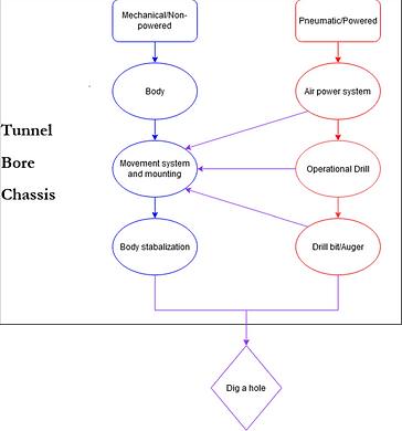
Flow Diagram

Design Analysis and Testing
The testing of our final product consisted of trial and error testing of each part individually and of the system as a whole. The first step in testing was testing our auger in a standard drill. The first tests included running the auger at different speeds to determine the auger’s stability at certain RPM’s. During this testing phase, we found that our auger was far more stable at lower RPM’s than at higher RPM’s while being operated by a battery-powered drill. The second test of our auger was to attempt to drill into the dirt with a battery-powered hand drill at low RPM’s. Packed dirt resulted in the first failure of our auger, which broke between the shaft of the auger the blade almost immediately. This break helped us recognize many stress points we had in our original auger design. These stress points were a 90-degree angle between the shaft of the auger and its blades.
Our second iteration of the auger was tested similarly after a couple of modifications made to reduce stress. These modifications included inserting a tap into the shaft and adding a fillet to any significant stress point. This auger ended up breaking at the point where the tap was inserted into the shaft. Our final auger design was then developed to strengthen the auger’s shaft by increasing its diameter to 1” and adding a premade hole for a metal rod in the middle of the shaft. These changes helped reinforce the auger’s strength and reduced the torque buildup’s stress from the drill chuck to the shaft. Though this design works well at digging a hole, we found through testing our drill that a metal dirt auger was much more fit for the job.
The first test of our drill was to determine if the modifications to it would be detrimental to its ability to operate. These tests were done after the modifications were made. These were simple tests of applying different levels of pressure to the drill to determine at what point it would stop operating. With these initial tests, we also used a small wood drill bit and a piece of wood to determine if the lowered torque and pressure would still allow us to drill into a substance. The final iteration of testing with our drill was with a metal auger. These tests included using different pressure levels to determine the amount of time we could dig for and how deep we could dig. Starting at 120 PSI, we could dig about 3” deep and for approximately 4 seconds before we lost enough torque to continue boring. At 90 PSI, we could only dig about 1.5” for around 2-3 seconds. With lower pressure resulting in diminishing returns. Our drill was only able to be tested while going straight down due to unforeseen circumstances, while our tunnel bore was designed to be used horizontally.
Finally, our movement system was only given a brief test at the beginning of manufacturing. This test included maintaining air pressure in the movement system and determining what PSI our gasket would blowout. Our movement system began to expand at approximately 15 PSI and would maintain pressure until 50 PSI, at which point the gasket was unable to maintain pressure. However, during assembly, we ran into a few complications with the movement system and lost the seal we were maintaining during the testing phase. We also ran into the complication of digging straight down, which our movement system was not designed to do.